Effect Pedal Circuits, Electronic Components, Electronics Tutorials, Operational Amplifiers
Electronics tutorials: the Operational Amplifier (II) – Circuit Analysis
In our first post about OpAmps we stated the basic principles of operation of this popular device. In this next issue let’s dive in directly into some of the most useful opamp circuits you’ll want to build for your audio projects!
1. OpAmp closed loop
Until now we had just analysed the opamp as an open loop device, where the signals were connected directly to the inputs with no extra electronic components. This is not practical as the open loop gain is way too high, so to build electronic amplifiers we need some kind of negative feedback that controls this gain in a predictable way. This is known as a closed loop opamp design.
In effect pedal kits these extra electronic components are resistors, and we’ll see in the next section through different examples how, by adding them the right way we can get the exact amount of gain we want, no matter the opamp open loop gain.
2. OpAmp Circuit examples
In this mode, we’ll use the two golden rules we made in our first post. Let’s remember them:
- The input differential voltage is zero in a closed loop design
- The inputs draw no current
To have a wide knowledge we’ll analyze three circuits: the opamp buffer, the opamp non-inverting amplifier and the opamp inverting amplifier.
2.1 – Opamp Buffer
The opamp buffer is the first circuit we’ll look at. With our two golden rules, it should be very straightforward: as there’s a negative feedback from the output to the V- input, we can consider V+ = V-. As V+ = Vin, and V- = Vout, Vin = Vout.
This is a simplified version of a buffer. In a real world case, like in our OpAmp buffer kit, there’s a few more parts that are needed for the circuit to work properly. To understand what the rest of the parts are and how they work along with this simplified version don’t miss our buffer post.
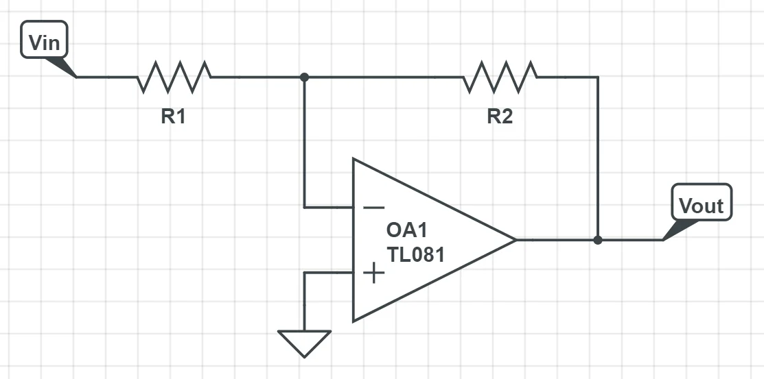
2.2 – OpAmp non-inverting amplifier
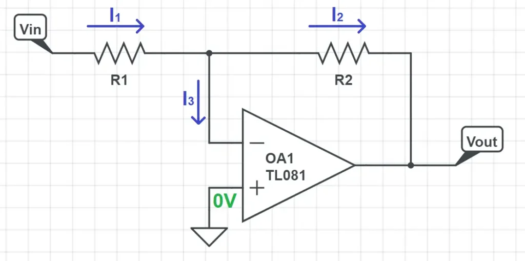
The non-inverting amplifier is one of the most common amplifier circuit configurations. It amplifies the input signal while keeping the same shape. To make easier the analysis, the following picture includes the voltages and currents to consider. This is always a good practice to have a clearer vision of the circuit:
The analysis is easy if you remember that the inputs draw no current (I3 = 0):
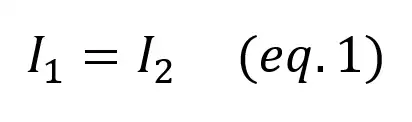
As V+ = V-, V- = Vin, using Kirchoff’s law,
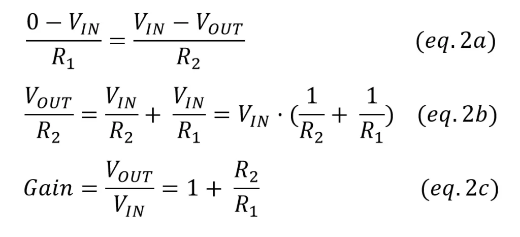
Our gain is given by G = 1+R2/R1, so an easy way to alter your circuit gain is to either lower R1 or increase R1. As we don’t want to draw too much current out of the opamp, usually R1 is in the 1k~10k range and R2 in the 47k~1M.
One particularity of this amplifier is that it can only be used as a volume booster. As the gain is given by 1+R2/R1 we’ll always have a gain greater than 1. The main benefit of this setting is that the input impedance is huge: it is the input impedance of the amplifier, which can have practical values of tenths or hundreds of megaOhms.
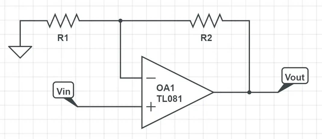
2.3 – OpAmp inverting amplifier
A common opamp inverting setting is the following one:
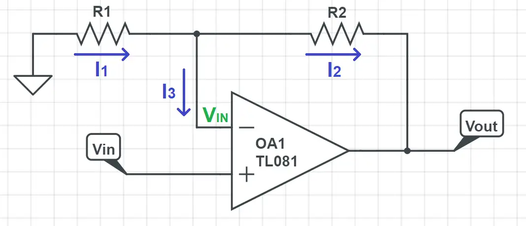
Now we’ll do the same analysis with the inverting amplifier. To check that you’ve understood how opamp circuit analysis is done we recommend you to try to find out what the gain is before continue reading.
In the next schematic we’ve added the different voltages and currents through the circuit:
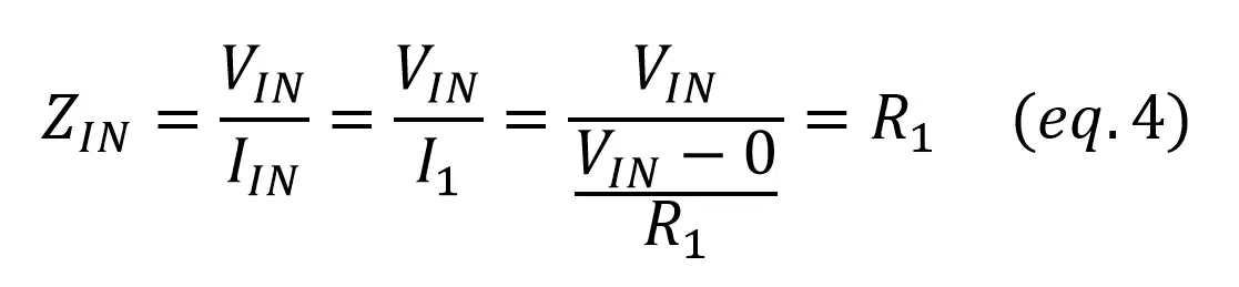
From the first golden rule, V- = V+ = Vx = 0V. From the second golden rule, I3 = 0 as the inputs don’t let any current pass through them. From Kirchoff’s current law,
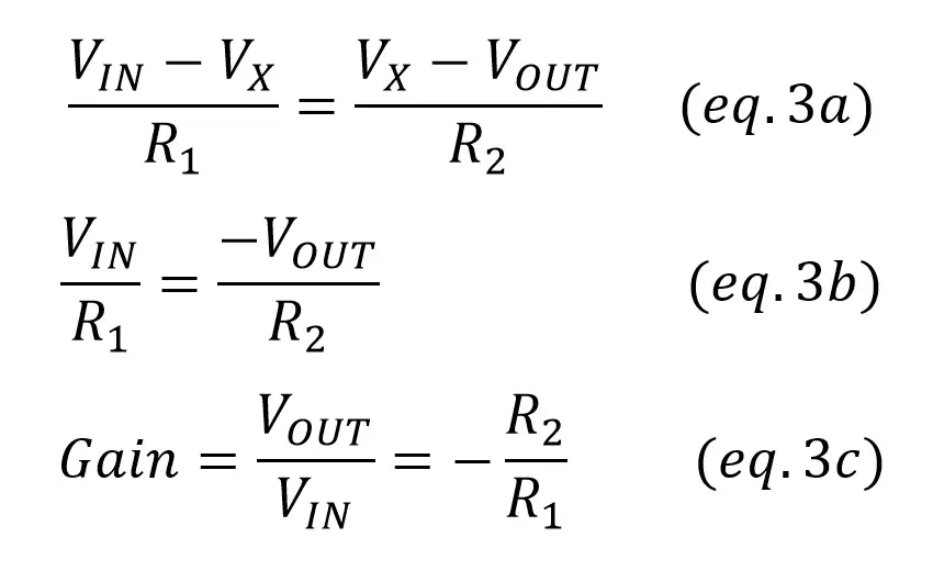
This means that we just need to adjust the ratio R2/R1 to get any gain we want. Usually the feedback resistor is in the range 47k-1M, as bigger values can induce too much noise (thermal noise) and lower values can produce too much current flow.
One important difference with the non-inverting amplifier: as we don’t have the “1 +” element in the gain, we can use the inverting opamp amplifier to boost (gain > 1) or to lower (gain < 1) the volume. The drawback is that now the input impedance is not almost infinite, but it depends on the resistors. In this particular configuration, the input impedance is R1: