Electronic Components, Electronics Tutorials, Operational Amplifiers
Electronics tutorials: the Operational Amplifier (I) – Basic concepts
OpAmps (short for Operational Amplifier) have been widely used in audio since their invention and production in the 1940s. Keep reading to learn more about these popular devices!
In this first post you’ll learn everything about OpAmps and the basic rules for circuit analysis. In the following post we’ll cover some circuit examples like amplifiers, buffers and more. Lets get’s started!
1 – Introduction
OpAmps (short for operational amplifier) are DC-coupled voltage amplifiers that take the input voltage difference and amplify it hundreds of thousands of times, and they are probably the most used analog circuit in electronics. Why are operational amplifiers so popular? There’s two basic reasons without going into the technical stuff:
- Thanks to their versatility they are widely used in almost any electronic application you can think of. Depending on the feedback components used (resistors, capacitors…) they can perform signal conditioning and filtering, integration and differentiation, oscillation and much more.
- OpAmp designs are way more stable than transistor designs. Put another OpAmp in your circuit (for example, switch a JRC4558 for a TL072 in your vintage TubeScreamer) and your circuit will keep working in the same way in almost 100% of the cases. Of course, in audio circuits some of the “sound color” can change, but imagine the other hand: change a J201 for another random JFET and in most of the cases your pedal won’t work at all. Put in other words, an opamp circuit relies almost totally in the design around the IC, while a transistor design relies a lot into the transistor properties.
2 – OpAmps: terms and principles of operation
2.1 – Operational Amplifier Pins
An Operational Amplifier is a three terminal voltage amplifier. It consists of two differential inputs with a huge input impedance, and a single ended output. Both input terminals are known as Non-inverting Input (Vin+) and Inverting Input (Vin-), and their difference (Vin+ – Vin-) is the differential input voltage.
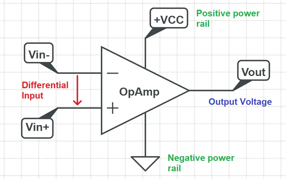
Vin+ and Vin- are the input pins. If we were considering a design for an effect pedal, here is where you would connect the output from your instrument. The input pins have a huge input impedance: a TL072, one of the most used opamps, has a typical input impedance of 10^12 Ohms. This is the impedance for the isolated IC in a lab environment: when we build circuits this impedance decreases, but still ranges in the tenths or even hundreds of Megaohms.
Vout is the output pin where we will get our amplified signal.
The power rail pins is where the power is connected. For effect pedal kits these values are almost always +9V for the positive rail and GND (0V) for the negative rail, except for some pedals that allow a higher power input. These values are very important: the output voltage will always remain between these power rails, so if we power the opamp at 0~9V, the output will always remain between these margins (more on this later).
2.2 – Gain and basic OpAmp equation
OpAmps inherent gain is known as Open Loop Gain (Aol from now on). This is the gain the amplifier would have if we connected our sound signal directly to V+ and V-, without any compensating feedback components. Aol has a huge value and it would be impossible to have any kind of usable amplifier that way, so in the next sections we’ll look at different ways to make OpAmps designs suitable for amplifying.
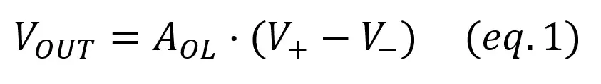
The basic OpAmp output equation looks like this:
Open loop gain is infinite in ideal opamps and can range from 50000 to 1000000 on real opamps.
2.3 – Power Rails
You also have to consider the power source voltage: an opamp will never be able to produce an output outside of the power range. The result of your calculations may say that the output voltage should be -4.5V, but if you’re powering the opamp with 0V~9V you’ll get 0 at the output. The same would apply to output voltages greater than 9V: even if you should get a 10V at the output, you will get a 9V signal as it is the maximum value the opamp can reach. Summing up: the output of the operational amplifier always remains within the power rails.
2.4 – OpAmp Basic Rules
These are the two golden rules you’ll need to analyse any OpAmp circuit:
a) In a closed loop the output will do whatever it takes to make the voltage difference between the inputs zero. b) The inputs draw no current.
Let’s explain them a little further:
Rule a) applies to any case where there’s some sort of feedback path from the output to the inverting input. This is what happens in amplifier designs; otherwise, as we explained in the first section, they would be unusable because of the huge open loop gain. With a negative feedback path we can set the gain to what we want.
To better understand it let’s consider a practical example of an opamp with a gain of 100000. If the opamp is powered with a 9V source it will be able to produce 9V at its output, tops. Then from equation 1,
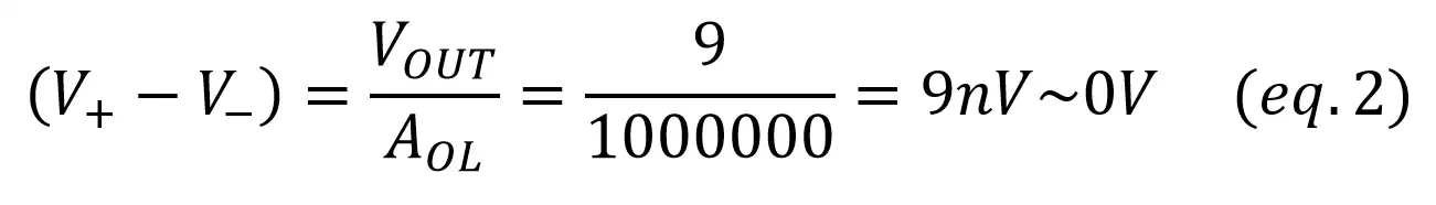
To produce maximum output, there’s only a difference of 9nV = 0.000000009V between the inputs. As this is a very small number we can make the approximation that the difference between V+ and V- is zero.
Rule b) means that we consider an ideal scenario where the opamp has infinite input impedance. In real world operational amplifiers inputs don’t have an infinite impedance, but it’s high enough to assume it as infinite.
2.5 – OpAmp open loop analysis
Operational amplifiers working in open loop are not useful for audio amplification purposes, but we’ll explain a basic circuit so you can understand how it works: the open loop signal comparator.
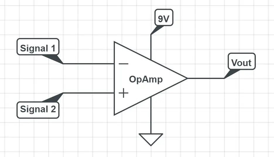
This simple opamp circuit takes the two input signals and returns:
- 0V if signal 1 is higher than signal 2
- 9V if signal 2 is higher than signal 1
In this circuit, one signal is fed to the V+ input and the other to the V- input, and the opamp is powered with a single +9V supply. The output will be given by:
Vout = Aol (V+ – V-) ≈ ∞ (V+ – V-)
That way, the output of the amplifier will be +9V if V+ > V- and 0V if V- > V+. This is how the output would look like if we had two input variable signals:
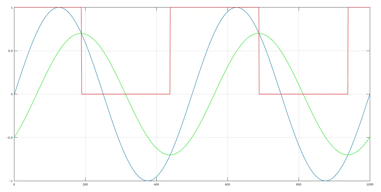
In this case, the blue line is signal 2 (Vin+), the green line is signal 1 (Vin-) and the red line is the output from the comparator. When the blue line is higher, the output is maximum and when the green line is higher the output is minimum. If you connect the output to a LED, you have an easy way to visually compare two signals!