Capacitors, Effect Pedal Circuits, Electronics Tutorials
Electronics Tutorials: the Capacitor (II)
In the previous post we presented one of the most used electronic components: the capacitor. Now we’ll learn to calculate capacitances and understand how capacitors are used in electronic circuits.
In the first section we’ll cover how to calculate capacitor grouping equivalent capacitance. This is very useful as in electronic circuits capacitors often appear in groups and replacing it with its equivalent capacitance is needed. In the second section we’ll review some of the capacitor uses in effect pedal circuits. Let’s dive in!
1 – Capacitor groupings
1.1 – Capacitors in parallel
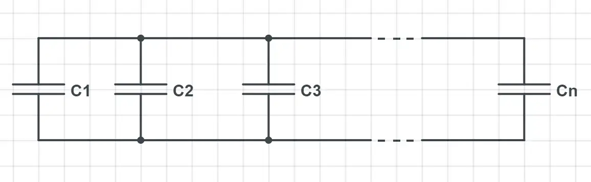
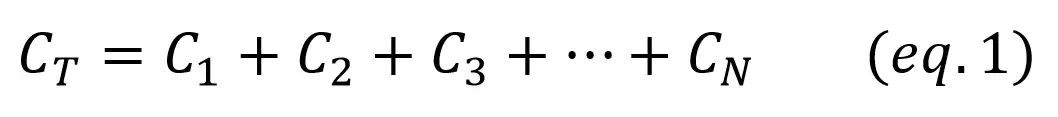
When all the capacitors are connected between two common points they are connected in parallel. If resistors in series were added directly, the same happens with parallel capacitors:
This is quite intuitive: placing them in parallel would be like having a bigger plate, and thus a bigger capacitance as these two values are directly related.
1.2 – Capacitors in series
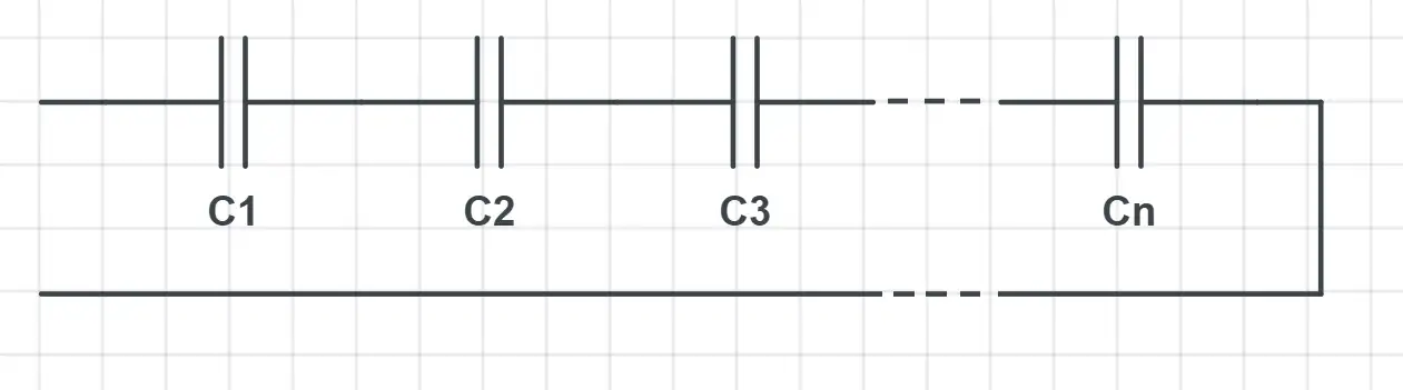
Two or more capacitors are connected in series if they are placed one after another. Capacitors in series are added with the same formula than parallel resistors:
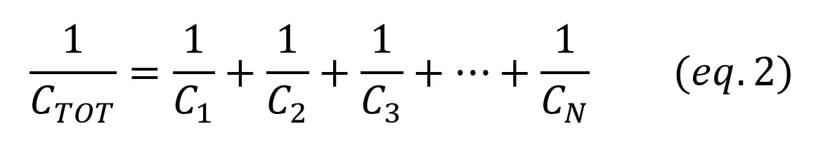
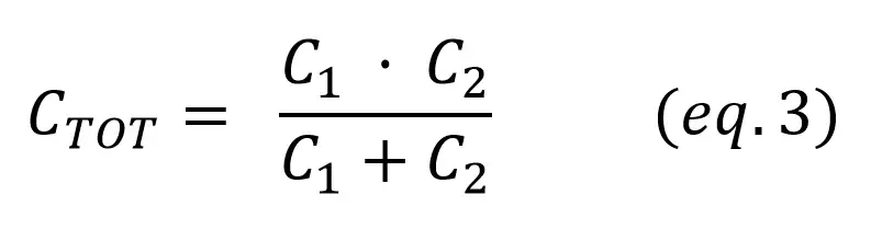
Likewise, if we only have two capacitors in series:
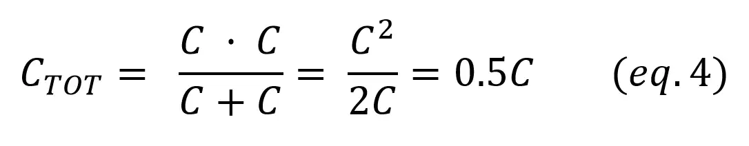
If both capacitors have the same capacitance,
2 – Capacitor circuit examples
2.1 – RC Low Pass Filter
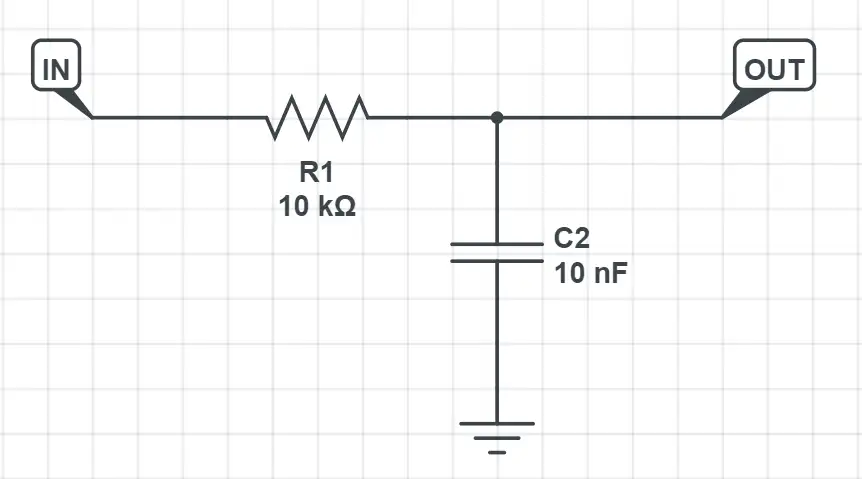
Filtering is one of the most important applications in effect pedal circuits: it allows us to remove and shape the sound by weakening or boosting some frequencies of the signal. The simplest low pass filter is achieved by using a resistor and a capacitor. This kind of filter will start removing frequencies higher than the cutoff frequency (fc). If we know the values of the resistor and capacitor we can get the cut frequency with this equation:
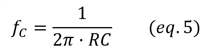
Example: we’ll analyse the low pass filter created with a 10k resistor and a 10nF capacitor. The cutoff frequency will be given by:
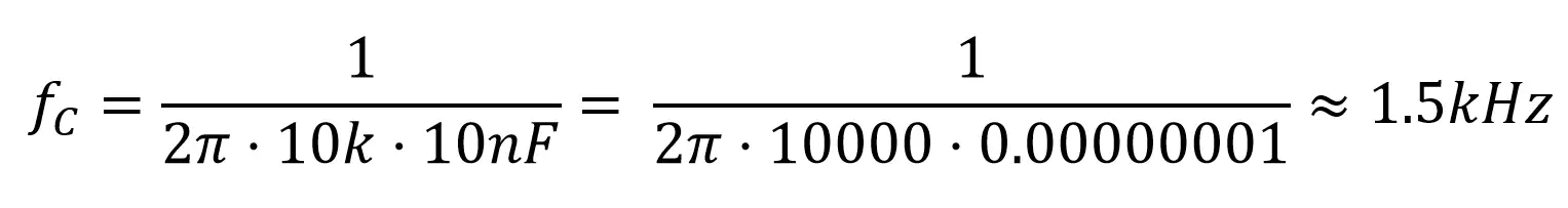
This is how the frequency response of this filter looks like:
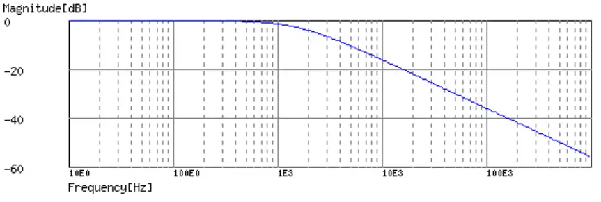
As you can see, at around 1.5kHz the frequency magnitude starts decreasing. This is not a sharp reduction: the high frequencies are removed more and more as we go into higher frequencies. In this example, at 4kHz we have -10dB of attenuation and at 20kHz we have -20dB.
2.2 – RC High Pass Filter
If we switch the resistor and the capacitor in the previous circuit we get a filter that reacts the opposite way: now only the low frequencies will be removed from the signal. The cut frequency is calculated with the same formula we used with low pass filters:
Example: 10k resistor, 10nF capacitor, fc~1.5kHz
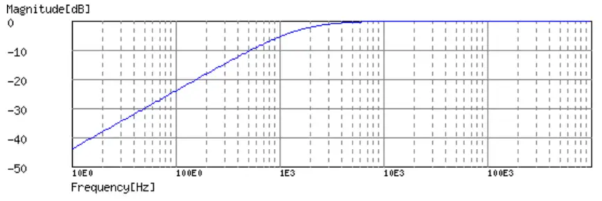
In this case the response is just the opposite: the frequencies are progressively lowered as we go into lower frequencies than the cutoff frequency.
2.3 – Coupling capacitors
A coupling capacitor, despite of its name, is no more than a standard capacitor placed in a way that it blocks the DC signal and allows the AC signal to pass through. Remember that a signal can be composed by:
– A DC part, that is constant and is only useful if we want to power some part of the circuit
– An AC part that carries the sound information
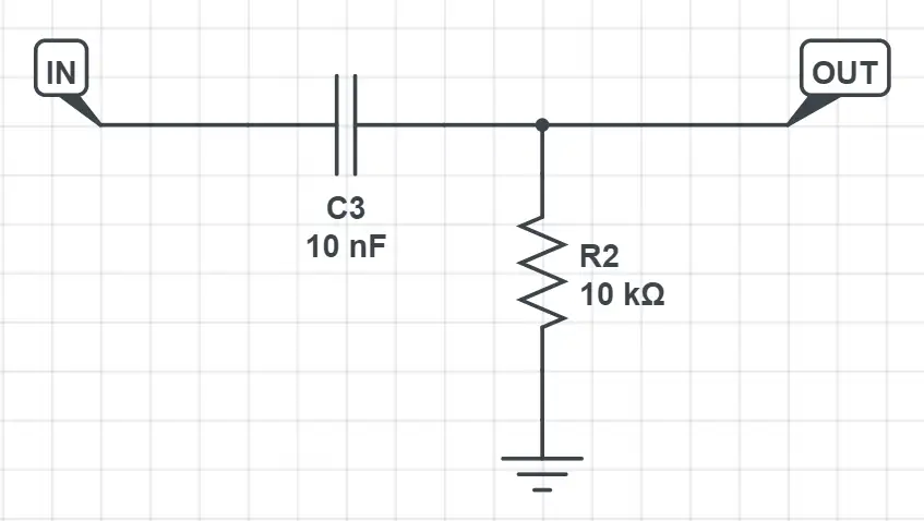
When building effect pedal circuits we often want to remove the DC part as it doesn’t hold any information and can cause different problems. In the next circuit, C3 is the coupling capacitor: it prevents any DC flow from the OpAmp to the JFET.
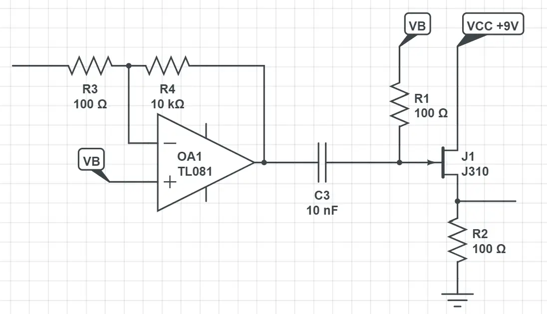
Coupling capacitors are widely used in effect pedal kits when going from one stage to the next one to prevent the DC signal to entering the second part of the circuit. For example, you can find them in the input of a buffer to block any external DC signal, or between the first and second stage of a distortion circuit.
2.4 – Decoupling capacitors
Decoupling capacitors (also known as bypass capacitors) are used in the opposite way than coupling capacitors: now we want to remove any AC signal and keep only the DC part. This is essential in power sources and power pins of ICs, otherwise the AC signal could cause unwanted noises or tickings in the output.
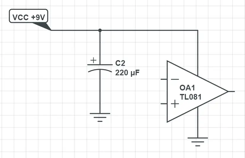
A common way to avoid these problems to use a big electrolytic capacitor (47-470uF) between the DC power line and the ground.