Capacitors, Electronic Components, Electronics Tutorials
Electronics Tutorials: the Capacitor (I)
Along with resistors, capacitors are the most used passive electronic component. If you’ve ever wondered how do they work and what uses they have in effect pedals (and electronics in general), keep reading!
As resistors, capacitors are passive two-terminal devices. But opposed to resistors, that consume energy, capacitors have the ability to store it in the form of electric charge. Actually, you can look at them like small batteries: once charged, they are able to deliver this energy to another part of the circuit.
Capacitance: how does a capacitor work?
While this is a very basic approach to capacitor theory (we don’t want to give you a headache!), it’s always good to have an idea how things work.
A capacitor is basically formed by two metal plates separated by a dielectric material. Dielectric materials are those who doesn’t allow current flow as they ideally have an infinite resistance.
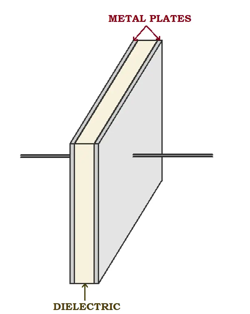
The capacitance depends on how much these plates are separated (a bigger separation produces a lower capacitance) and the relative dielectric permittivity of the material (the bigger the dielectric constant the bigger the capacitance):
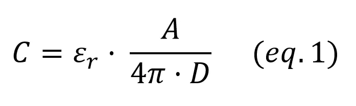
Where:
- A: Area of the plates
- D: Distance between the plates (dielectric thickness)
Capacitance is measured in Farads, but this is a quite large unit: the capacitors you’ll find in our effect pedals kits range from a few picoFarads (10^-12 F) to some hundreds of microFarads (10^-6 F).
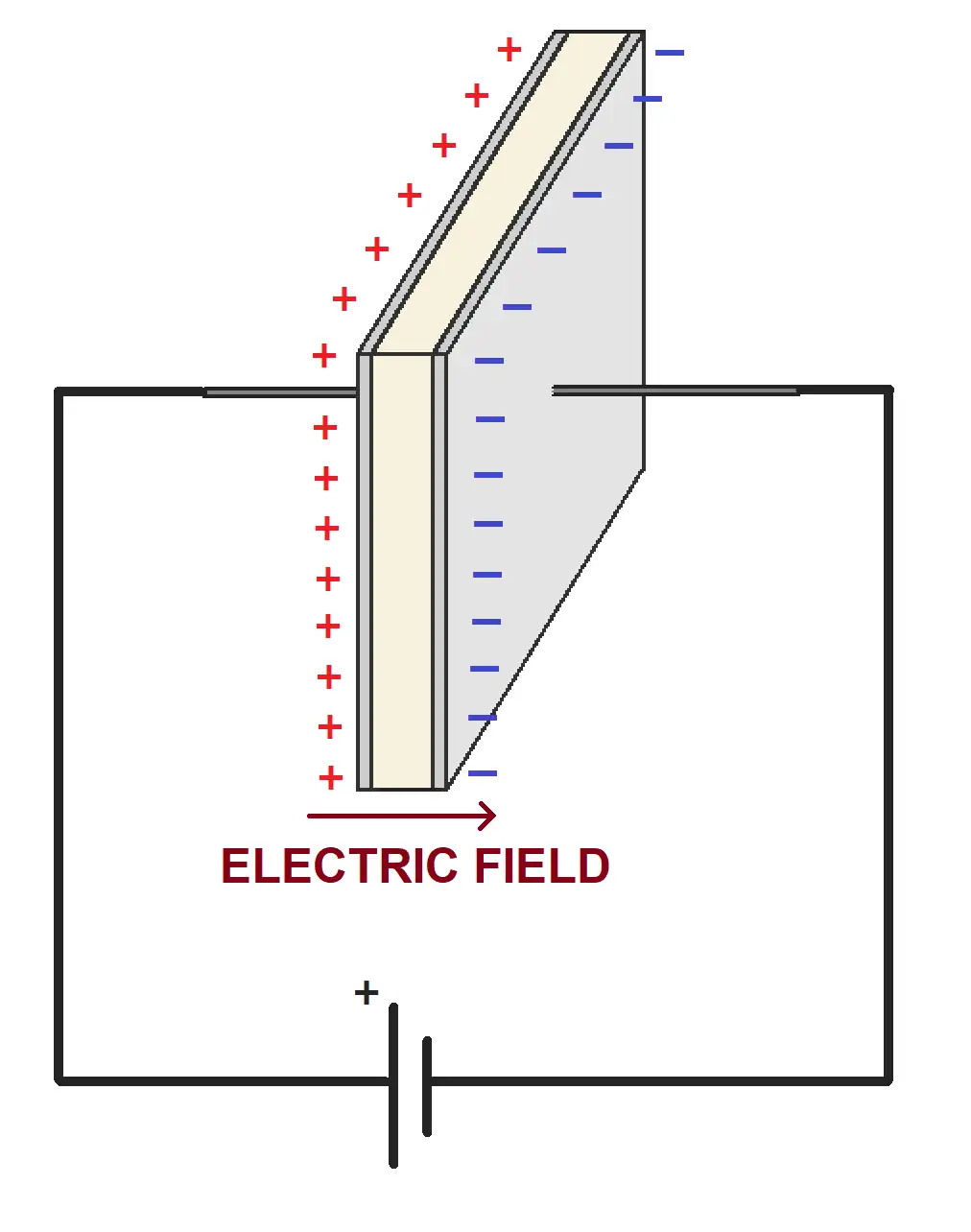
If a voltage is applied between the plates of the capacitor, electrons stock in the metal planes. Like the magnetic force that attracts two magnets of different sign, these electrons produce an electric field. If they were floating, both plates would join together because of this attraction, but we have a dielectric in between: the plates are stuck in their place.
This is how energy is stored in capacitors. When something else is connected to the capacitor, these electrons are “released” back into the circuit.
Polarized vs non-polarized capacitors
Unlike resistors, not every capacitor is symmetrical. Depending on how they are made, there’s capacitors which pins are interchangeable (mostly ceramic, polyester) and some which pins must be connected in a specific way (electrolytics).
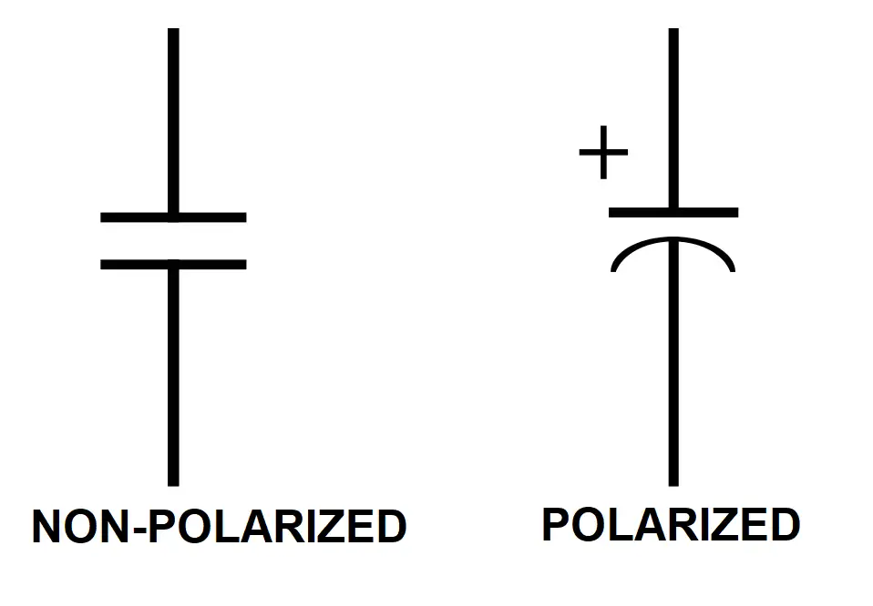
Last ones are known as polarized capacitors. They have some kind of marking in the enclosure that tells you which terminal must be connected to the most positive voltage (anode) and which one to the most negative voltage (cathode).
You’ll be able to recognize polarized capacitors in a schematic because they have a different symbol that lets you know how they should be connected.
Capacitor important parameters
1 – Capacitance
A capacitor’s capacitance is its most important parameter. When designing a circuit this will be the first specification you’ll be looking for. As we explained in the previous section, the capacitance depends only on the geometry and dielectric material of the capacitor and represents its ability to store electrical energy. Learn how to read capacitor values in this post!
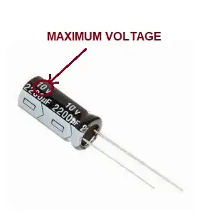
2 – Maximum voltage
This is a critical parameter when building a circuit: a capacitor has a maximum voltage it can tolerate. Apply a potential over this value and depending of the capacitor it may just internally burn or literally explode in your face (electrolytics are particularly noisy!).
This maximum voltage can be read from the marking in the capacitor. Capacitors other than electrolytics (polyester, ceramic…) are usually rated for above 50V so in general their maximum voltage won’t be critical.
In our effect pedal kits we always pick capacitors with a way higher voltage than the one they’ll have to face in the circuit. If you’re only getting the PCB and buying the parts on your own, be sure to check maximum voltage values specially for electrolytic capacitors!
3 – Capacitor tolerance
[As resistors], capacitors also have a tolerance, that is the deviation of the real value from the ideal value. This value appears usually in the capacitor marking. Check our capacitance calculator to find the value of your capacitor.
Example: a 10uF capacitor with a 10% tolerance will range from 9uF to 11uF.
Types of capacitors
Even if they use the same working principle, not all capacitors are made from the same materials. Different applications look for different properties in capacitors, and because of that we have different types of them. These are the most common:
- Ceramic capacitors: they are ususally small, cheap, and allow big maximum voltages. They are commonly used in high frequency applications. Their drawbacks: ceramic capacitors have a small capacitance and don’t are very stable against temperature.
- Polyester capacitors: plastic films offer better stability than ceramic, and are a good choice when bigger capacitances and stability are required.
- Electrolytic aluminium capacitors: these are your best choice if you’re looking for huge capacitances! They also allow high voltages, but they have a drawback: their specs aren’t as good as their ceramic or polyester counterparts (specially the tolerance and ESR).