Electronic Concepts, Electronics Tutorials
Electronics Tutorials: Power in electronic circuits
Power is a basic measure that lets you know how much energy your effect pedal (or other electronic circuit) is consuming. This is very important when using a power source or designing a pedalboard. In this post we’ll look at how to analyse basic electric circuits to know how much power they consume.
If you want to dig deeper into electric power, we’ll look at different electronic circuits and how you can find out the power consumed by the different elements. To keep things relatively simple the circuits will only be formed by power sources and resistors, the only passive element that consumes power. If you struggle with anything, with some basic resistor concepts and Ohm’s Law you should have all the tools you need to go through these examples!
1 – Simple circuit
Consider this simple circuit: a resistor and a DC 9V generator.
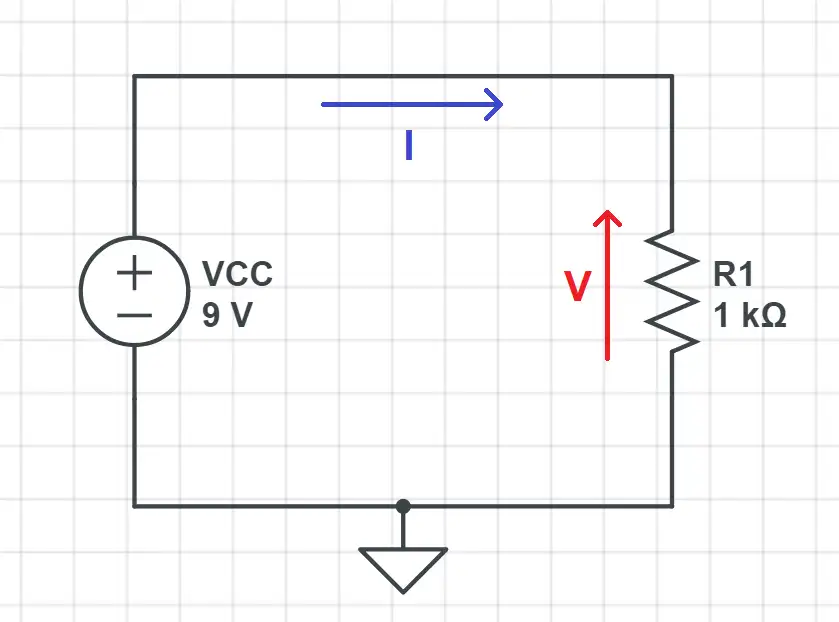
To know the power consumed by the resistor we need to know the voltage across it and the current flowing through it. The voltage is directly VCC = 9V, as the resistor is connected directly to the voltage generator.
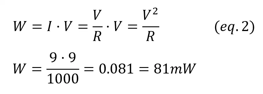
Now we can get the current flowing through the resistor if we use Ohm’s Law (I = V/R). That’s all we need to calculate the power!
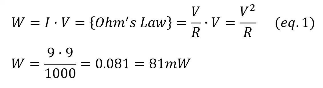
On the other hand, the power source is generating energy as it is “throwing” the current into the circuit. The voltage across the source is VCC = 9V, and the current is the same that flows through the resistor (I=V/R). The amount of power generated is:
To know if a device generates or consumes power you just have to ask yourself this question: if you changed every other device by a piece of wire, would the current still flow?
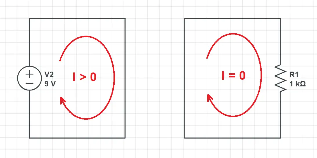
Battery: if we replaced the resistor by a wire the current would still flow. The battery or DC power adapter generates power (left).
Resistor: if we replaced the battery by a wire we would have no current as the resistor is a passive device unable to generate energy: it only consumes the energy generated by the source (right).
As there’s only two elements in the circuit, the power consumed by one is the same as the power generated by the other.
2 – Shared current (devices in series)
Now let’s look at a second schematic:
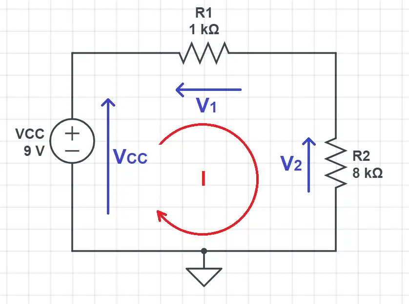
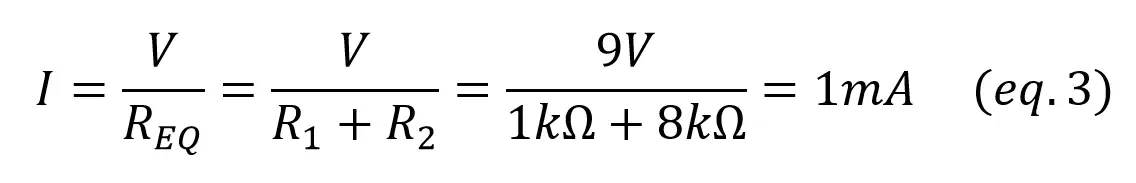
The current through all the devices is the same as they are in series. We can calculate it using Ohm’s Law and the [equivalent series resistor]:
To calculate the voltage in R1 and R2 you just have to notice how they form a voltage divider.
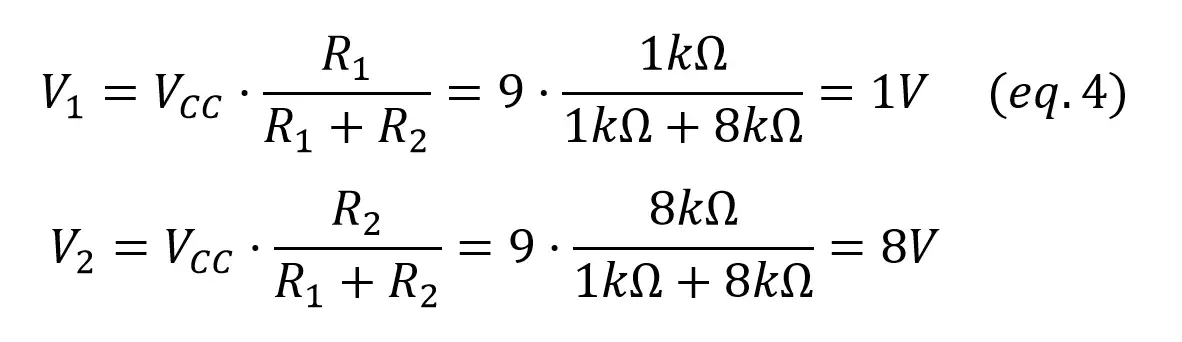
To be sure that there are no errors always check that VCC = V1 + V2. Now the power consumed by each resistor is given by:
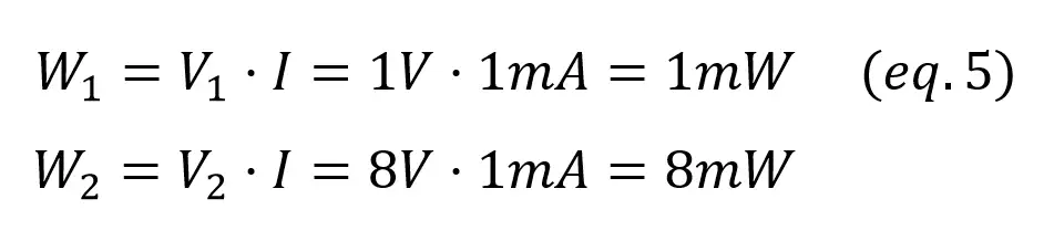
As for the power source,
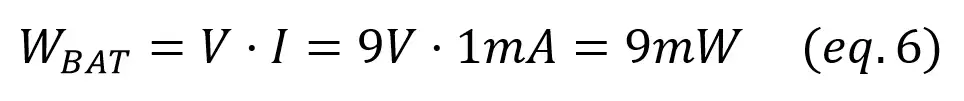
In this example we have two resistors, so the total generated power (9mW) is divided between R1 (1mW) and R2 (8mW).
3 – Shared voltage (devices in parallel)
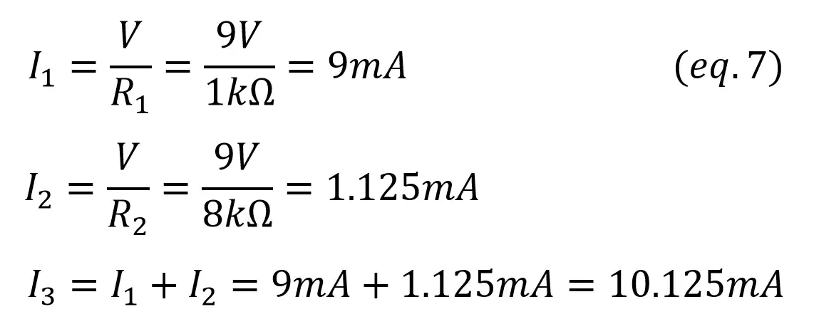
In this case the resistors are placed in parallel. We’ll start by calculating currents I1 and I2, as we know the voltage across both resistors (VCC). By using Kirchoff’s current law we can also calculate I3 as I1+I2.
Now we find the power in the resistors and source:
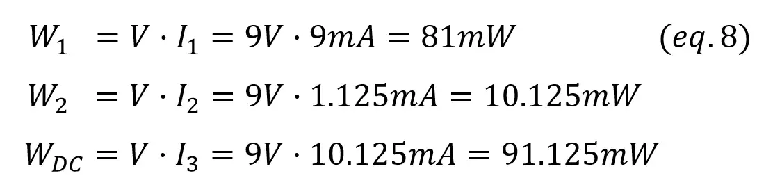
As in the previous examples, the total power generated (Wdc) is the sum of all the power consumed (W1 and W2).
4 – Mixed parallel & series resistors
This is the hardest case! Now we have parallel and series resistors so we’ll have to take extra steps. First of all, you need to understand the relations between currents and voltages:
- The voltage across R2 and R3 is the same (V2)
- The current through the power source and R1 is the same (I1)
Now you can use Kirchoff’s Law to establish the relations:
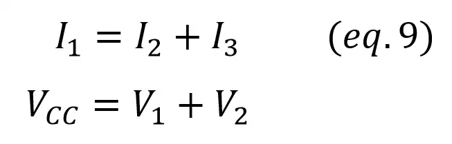
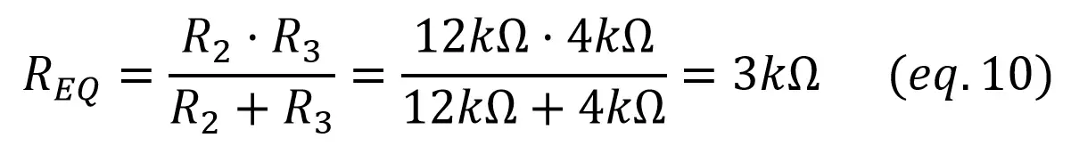
To calculate V2 and I3, it would be easier if we could reduce the circuit to something simpler. To do that, Req can be calculated as the parallel of R2 and R3:
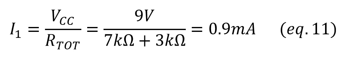
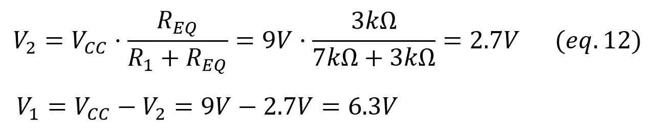
With Req, you can find I1 as the total current through R2 and R3 (Req) like we did in example 2, and V2 with a voltage divider. Once we have V2, V1 is calculated with Kirchoff’s voltage law (VCC = V1 + V2):
As now we have the voltage across R2 and R3, we can find the current through them using Ohm’s Law:
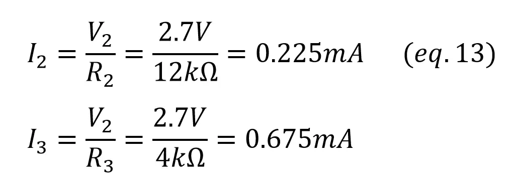
To be sure that there’s no mistakes, always check that I1 = I2 + I3!
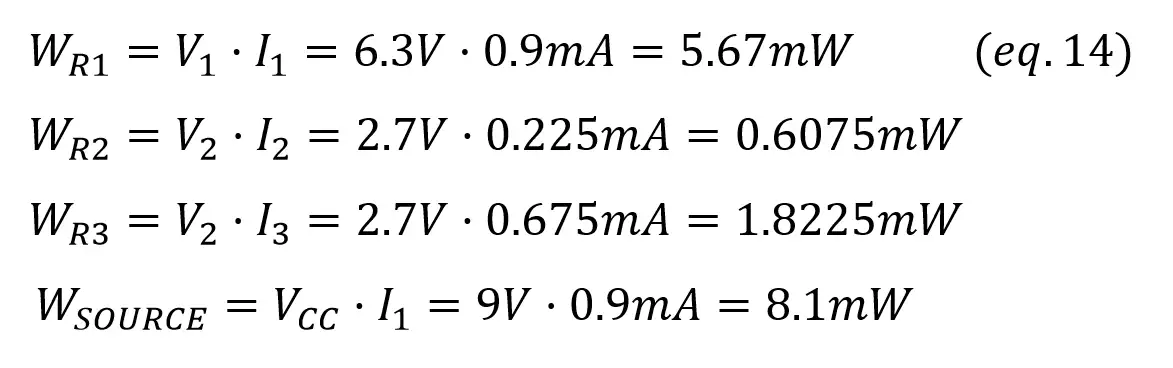
With all the voltage and current values, finding the power consumed by each element is easy: