Electronic Concepts, Electronics Tutorials
Electronics Tutorials: Basic electronic concepts
What’s a voltage? Have you heard about Kirchoff’s laws? Keep reading and you’ll learn the very basics to understand electric circuits.
1 – Voltage
Voltage, or potential difference between two points, is the “motor” that make our effect pedals work. It represents the force that tries to make a current flow between these two points. Batteries or DC power adapters are some example of voltage generators. It’s measured in volts.
An approximated analogy would be a water tank that had a pipe towards the ground. The height of the tank would represent the voltage: if the tank is taller, the pressure at the bottom is bigger. Nevertheless, no water can flow if we keep the pipe closed.
We’ll use this schematic to explain a few concepts:
1 – In a circuit, the voltage across a whole wire is considered constant.
2 – Voltage, even when it is not stated explicitly, is always a difference between two points. As it’s easier to give a voltage using only one point, in electronic circuits we always pick a point known as ground (often shorted GND in electronics). This point is our voltage 0V reference, and when no second voltage is given, this voltage is referenced to GND. Let’s see some examples:
- Va → Va – Vc
- Vb → Vb – Vc
If we say Va = 7V, we are implying that the voltage difference between A and C is 7V. If there was an “absolute voltage” we could as well have Va = 7V & Vc = 0V or Va = 100V & Vc = 93V. The importance is that the difference between them is 7V.
3 – Many times in circuit analysis it’s interesting to have the voltage difference between the pins of a part. This is known as the voltage drop of this element and is usually displayed with an arrow on the side of this part. The arrow points to the side where the voltage is higher:
- V1 = Va – Vb, where Va > Vb (the arrow points towards A)
- V2 = Vb – Vc = Vb as Vc is the voltage reference.
2 – Current
Current is the flow of electric charge through a circuit. When there’s a voltage between two points, if a resistance is present between them a current will flow. Current is measured in Amperes (A).
Continuing our analogy, we open the pipe: now we have a water stream flowing. This would be the current in our electric circuit. Depending on the pipe diameter we will have more or less water flowing: a smaller diameter will create a higher resistance to water flow and thus the stream will be smaller. The pipe size would represent the circuit resistance to current flow.
As this example is a closed loop, according to Kirchoff’s current law, the current through all the elements is the same (we’ll explain this further in the next section).
The arrow represents what is called the “conventional current flow“: the current goes from positive to negative terminal of the power source.
2.1 – Ohm’s Law
Ohm’s law states that, given a potential difference V between two points (also known as voltage) and a resistance R between them, a current will flow. The relationship between these parameters is:
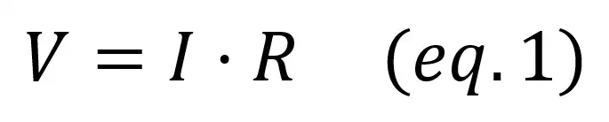
This law also applies to physics with more complex forms, as the previous equation is a simplification for electronic circuits.
2.2 – Kirchoff’s law
The two Kirchoff’s circuit laws are a fundamental tool that allow you to analyse electronic circuits through current and voltages relations. With both of them you will be able to find out the different equations that govern a circuit and find all the unknown voltages and currents.
2.2.1 – Kirchoff’s current law
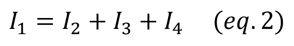
Also called Kirchoff’s first law, it states that the sum of currents entering a node equals the sum of currents exiting it.
Continuing our previous example with pipes, the total amount of water that enters any point must be equal to the amount of water that exits it.
2.2.2. Kirchoff’s voltage law
Kirchoff’s second law says that, in any closed loop, the sum of electrical potentials or voltages is zero.
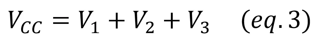
Another way of looking at it might be more intuitive: the sum of all potential increases (for example batteries or DC sources) equals all the voltage drops (for example resistors or capacitors).
3 – Power
3.1 – Concepts
Electric power is the rate at which electric energy flows to an electrical circuit, or energy per second. It represents the “work” that has to be done to make the current flow through all the electronic components in the circuit, and is measured in Watts (W). To produce electric power you need an active device like a power source or a battery. Passive devices, in the other hand, can only consume power.
Power can be calculated from the voltage V applied to the circuit and the current I that flows through it with the following expression:
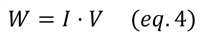
Power will be positive for active devices or generators (they generate the energy) and negative for passive devices or loads (they consume the power).
3.2 – Power sum in circuits
Electric power is very important when building your pedalboard. More often than not any power supply will be able to deliver the necessary power to a single pedal, but if you are powering many of them from a single DC adapter you have to be sure to know how much power your effects consume.
For example if you have an effect pedal that sinks 20mA of current and it’s powered with a 9V power adapter, it consumes 0.18W. In general analog pedals (like a booster) consume less power than digital pedals (like the echo delay, that includes a digital IC to generate the delay).
Once you know how much power is consumed by every single pedal, you just have to add them together and you’ll find how much power you need for your supply:

Getting started into electronics might seem a bit overwhelming at the beginning, but with these concepts you’ll get a grasp of the basic ideas and tools you’ll need to understand effect pedals circuits and any other electronic schematic you want to analyse. Don’t miss our other Electronics Tutorials posts!