Effect Pedal Circuits
How to read a Veroboard?
When you first look at a veroboard layout, it might feel like you’re decoding some kind of cryptic map. All those dots, lines, and symbols… what do they actually mean? Learning how to read and work with veroboard schematics is a key skill for any DIY pedal builder, especially to those interested in modifying existing pedals or even testing a first version of their own. While a bit unintuitive at the beginning, once it clicks, it opens up a whole world of tone experiments!
1. Introduction
Veroboards (also known as stripboards) are kind of like the bread and butter of DIY guitar effects. They give you a flexible way to build circuits without having to design a custom PCB, which is why they’ve been a favorite among hobbyists for decades.
If you’re just getting into pedal building, vero layouts might seem a little intimidating at first, especially when compared to plugging parts into a labeled PCB. But once you understand how to read them—and what all the symbols and lines mean—you’ll be able to build some amazing pedals using just a strip of copper and a few components.
Let’s break it all down!
2. What’s a Veroboard, anyway?
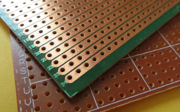
A veroboard is a thin board with a grid of holes, and running along the back side are copper strips that act as electrical paths. Each row (usually horizontal) is a continuous copper track, and each column (vertical) is simply an isolated hole.
The basic idea is that you place components on one side of the board (the component side), and the copper tracks on the other side handle the connections. To shape the circuit, you’ll cut some of those copper strips where you don’t want current to flow, and add jumper wires where you need to bridge connections.
Compared to PCBs, where the layout is already printed for you and everything’s labeled, veroboards give you a lot of freedom, but they also ask a bit more from you as a builder. You’re wiring the “streets” yourself instead of following a pre-built map.
3. Decoding Vero Layouts
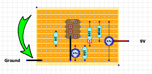
The most common way to build from a veroboard layout is to follow a diagram. This is usually a grid that shows a top-down view of the component side of the board. These diagrams pack a lot of info into a small space, so understanding the basic symbols is key. The most standard way of designing these are using the copper strips as rows, but some might place them as columns.
- Dots or crosses usually mark copper track cuts. You’ll be drilling or cutting these with a blade to break the strip.
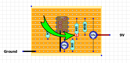
- Lines going over the layout represent jumpers, which are short wires bridging connections across rows.
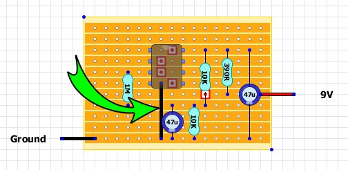
- Colored shapes represent components. Resistors, capacitors, diodes, and ICs are usually color-coded or shaped to make them easier to tell apart.
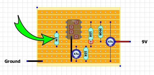
- Wires that go out of the stripboard represent connections to other elements that are not in the board like power, jacks or potentiometers.
Once you get used to these layouts, reading them becomes second nature. Still, it’s easy to make a mistake if you misread the orientation, especially when flipping the board to cut the copper strips. Many beginners accidentally mirror the layout when working on the backside. PCBs remove that whole step, because everything is already routed and labeled for you. Also, while veroboards are great to prototype and test, PCBs are better regarding noise and hum if you are looking for a definitive pedal.
4. Step-by-Step: Reading a Vero Layout
So, how do you actually follow a vero layout? Here’s a simple flow:
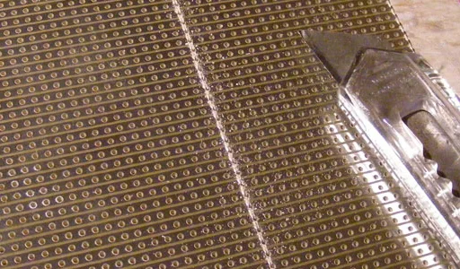
- Orient the board and cut it to the right size: Make sure you’re holding it the same way as the layout (usually with the copper tracks running left to right). Then, cut it to the desired size (in the previous section, 11 rows x 16 columns).
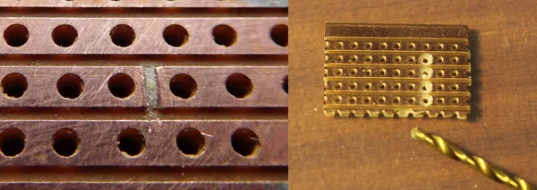
- Mark and cut the tracks: Use a small drill bit (right), blade, or a vero cutter tool (left) to break the copper tracks exactly where the diagram shows. You can test these cuts with a multimeter to make sure they’re truly isolated.
- Add jumpers: Solder in small wire jumpers where indicated. Jumpers are added into the component side.
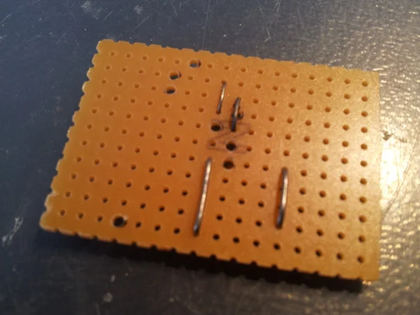
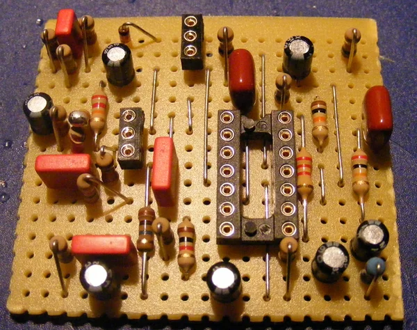
- Place components: Start placing resistors, caps, diodes, etc., into the exact holes shown on the layout. Bend the leads underneath, then solder them to the copper strips. It’s useful to start from lower profile (resistors, diodes) to higher profile (capacitors, transistors…). If you are using ICs for your circuit, using sockets is a great idea!
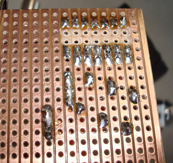
- Solder cleanly: Make sure your solder joints are solid and not bridging adjacent tracks by accident.
It’s a more hands-on process than building on a PCB, where components are often labeled directly on the board and you don’t need to worry about cuts or jumpers. But vero also gives you the freedom to tweak, mod, and experiment.
4. Common mistakes (and how to avoid them!)
If you’re new to veroboard, here are a few common hiccups to watch out for:
- Missing or incorrect track cuts: One missed cut can completely mess with your circuit. Double-check them before placing components. If you have a multimeter, check continuity to be sure that your cut is clean!
- Misplaced jumpers: Jumpers look simple but can be easy to overlook or be placed in the wrong position. Mark them off as you go.
- Component orientation errors: Diodes, transistors, ICs all have a specific direction. Plug them in backward, and the circuit might not work (or worse!).
- Flipping the board: When cutting or soldering, make sure you don’t flip the board and mirror the layout by accident. Marking the edges can help.
PCBs avoid most of these issues by guiding your hand every step of the way. But vero does teach you the circuit in a deeper way (mistakes included!).
In following posts we’ll perform all these steps to build a pedal in a veroboard from scratch. Stay tuned!