Electronic Components, Electronics Tutorials, Resistors
Electronics Tutorials: the Resistor
Resistors are one of the most widely used passive electronic components. Resistance, tolerance, power dissipation… Dive in and learn everything about them!
1- Resistor basics
First of all, resistors are passive devices, meaning that they can’t generate power as transistors or opamps, they can only consume it. Resistors have two terminals and work by presenting a constant resistance to current flow in an electronic circuits. They are symmetrical devices: you can connect them either way and work the same way.
1.1 – Resistance
If current flow in a circuit was represented by a water flow through a pipe, resistance could be compared to the pipe size: a pipe with a smaller diameter would create more resistance to water and the “water stream” would be smaller.
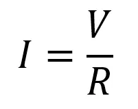
A resistor’s resistance is its most important parameter, and it’s measured in Ohms (Ω). The definition of 1Ω is the resistance needed to produce a current flow of 1A when connected to a 1V power source. The relation between V, I and R is given by Ohm’s Law (POST):
1.2 – Power dissipation
The maximum power a resistor can dissipate is also an important parameter: exceed it and you can burn and permanently damage the resistor!
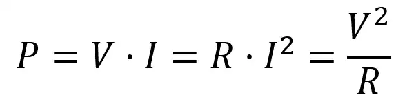
Power dissipation, as you’ll recall from our electronic basics post, is given by:
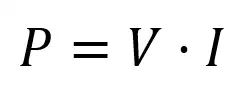
Using the Ohm’s law, we can either replace V = I·R or the equivalent I = V/R
Usual resistors you’ll find in effect pedal circuits will be rated for 1/4W, which is more than enough.
1.3 – Tolerance
The last important resistor parameter we’ll review is resistance tolerance. Ideal resistors would always have the exact same resistance value, but in real resistors there is a difference between their theoretical value and their real one. The maximum difference you’ll find between the resistor nominal and real values is the resistor tolerance.
Tolerance is not an absolute value but a percentage: a 10kΩ resistor with 1% tolerance will have a maximum deviation of 100Ω (1%·10kΩ = 100Ω), so you can expect your real value to be in the range 9.9kΩ (10kΩ – 100Ω) and 10.1kΩ (10kΩ + 100Ω).
Tolerance value is marked in the last color band of the resistor:
– brown: 1% – gold: 5% – silver: 10%
In our effect pedals we use 1% resistors.
2 – Grouping resistors
When analyzing circuits you’ll often find groups of resistors together, and to go on it’s usually easier to group them as an equivalent resistor. By the time you finish this section you’ll be able to simplify resistor circuits by grouping them in either series or parallel equivalents.
2.1 – Series resistors
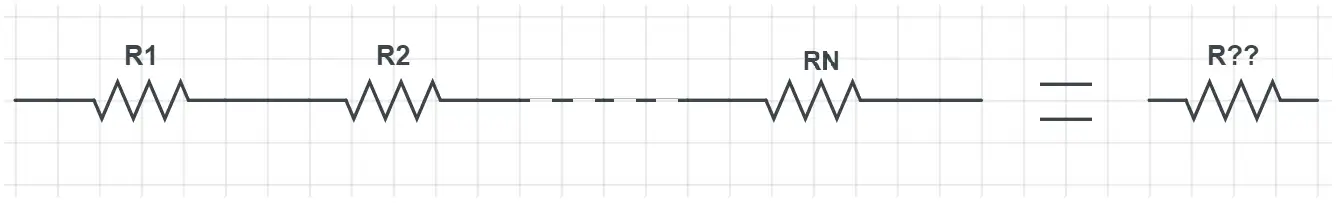
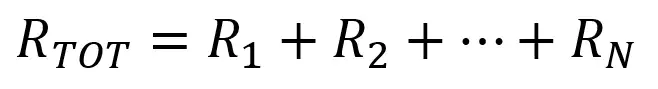
If resistors are connected one after the other we say they are connected in series. In this case it’s very easy to find the equivalent resistor: we just have to add all the values together:
2.2 – Paralel resistors
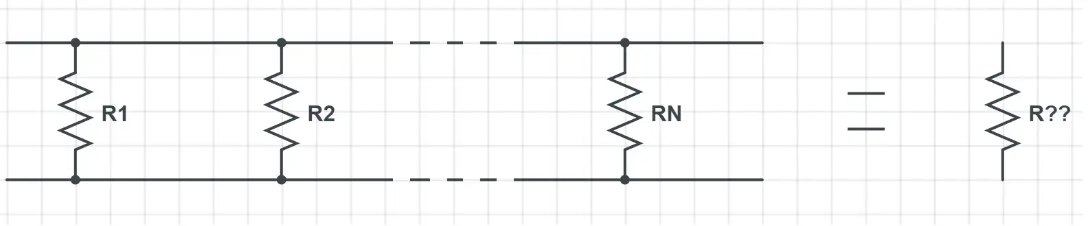
If their pins are connected to two common points the resistors are connected in parallel. In this case the equivalent resistance is not so easy to calculate:
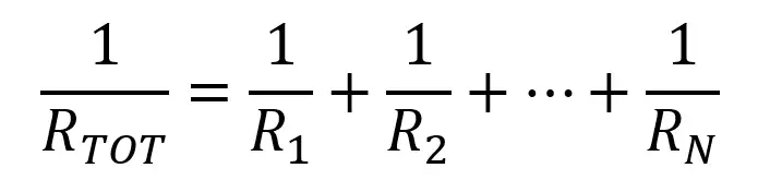
This formula gets simpler when there’s only two resistors:
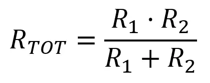
One particular ocurrence is if R1 = R2 = R. In that case, the formula becomes:
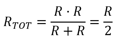
That’s an easy and useful way to get a resistor with half the value!
3 – Example circuits
3.1 – Limiting resistor
A very useful application for a resistor is as a current limiter. Imagine the case of an effect pedal kit; the voltage is fixed, usually at 9V or maybe at 18V in some cases, but a constant value. As current and voltage are related through Ohm’s Law (equation 1), if voltage is fixed we can calculate a resistor for a maximum value of current. Some devices, as LEDs or diodes, can be damaged if too much current flows through them and a limiting resistor is mandatory in such cases.
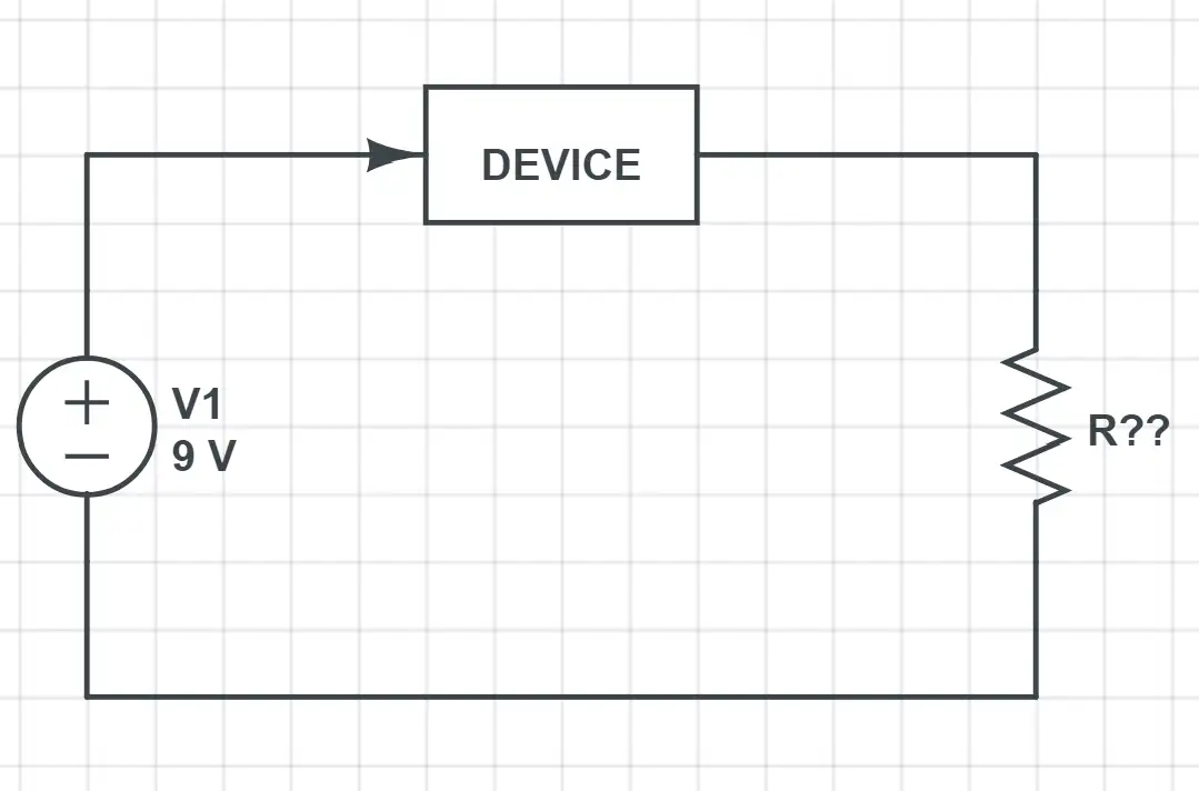
For example, let’s say that in the previous circuit we have to calculate the limiting resistor for a maximum current of 10mA. These are the main points to consider:
- We are looking for a resistor that allows a maximum value of current. This is the same as saying that we want to calculate the resistor’s minimum value: as current and resistance are inversely related, more resistance means less current.
- Devices in a circuit create a voltage drop (the 9V are split between the device and the resistor). But as we want to analyze the worst case, we’ll assume all the voltage drops at the resistor.
Then, with our Ohm’s Law equation,
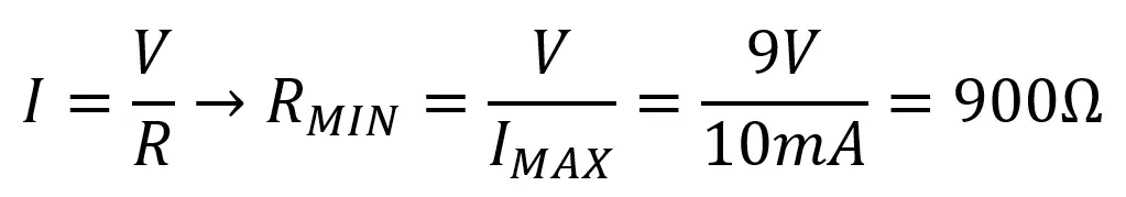
To ensure that the maximum current flowing through the circuit is 10mA we have to use a resistor of at least 900Ω.
3.2 – Voltage divider
The voltage divider is very useful in effect pedals, and you’ll find it in the input of almost any JFET or OpAmp. It allows us to produce a voltage that is a fraction of the input voltage. This is essential as the signal coming from our instruments is referenced to ground (it swings from positive to negative) but in our circuits we only have positive voltages, so we need to add a certain amount of offset.
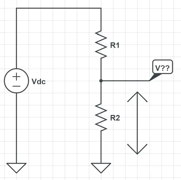
The unknown voltage is V??. When no other reference is given, we’ll be looking for the voltage between the place in the circuit and ground. In this circuit V?? represents the voltage between the common point of R1 and R2, and ground. This is the same as the voltage across R2.
In a circuit like the previous one the voltage across R2 will be given by the following equation:
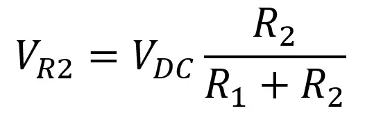
To understand the meaning behind this equation just imagine that each resistor “takes” a voltage proportional to their resistance: if both have the same value the voltage across each one will be 0.5·Vdc, if R1 is 9kΩ and R2 is 1kΩ V?? will be 0.1·Vdc and so on.
In the input of our JFET buffer you can see this circuit in a real world application:
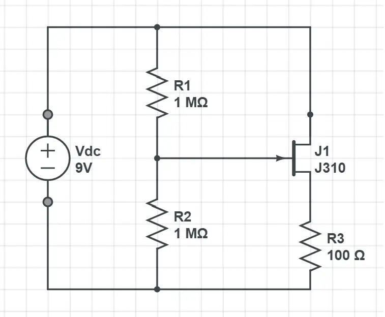
By using the previous equation with the right values:
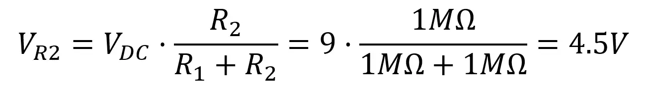
You’ll find this kind of configuration a lot in effect pedal circuits: thanks to it the sound signal from our instrument will fall within the power margins. In the next picture we’ve illustrated the original sound signal and the one obtained after the voltage adding.
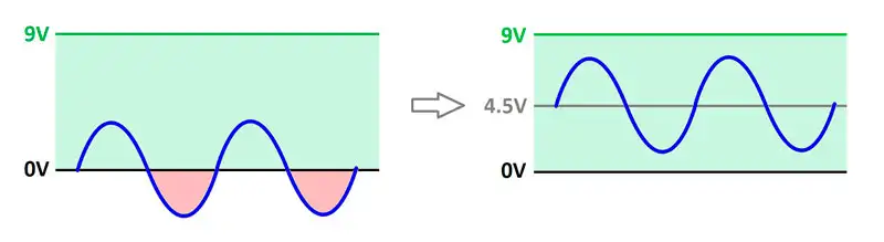
The left picture represents the signal as it comes from either a guitar or a bass: it’s centered around 0V. But our power region is between 0V and 9V: this means that any part of the signal that falls out of this margin won’t be amplified / modulated / boosted as it should. That is why we use a voltage divider as the one we’ve just analyzed to add a constant amount of half our power voltage to the input signal.