Effect Pedal Circuits
Gain effect pedals: distortion, overdrive and fuzz
Gain effect pedals include multiple families of circuits; the most important ones are boosters, overdrives, distortions and fuzzes. All these pedals have different “stages”: gain, clipping and filtering. Two of them are very similar across all the pedal families, while one of them is the main responsible of the tonal differences between them. Keep reading and find out more about these pedals!
1 – Introduction to gain effect pedals
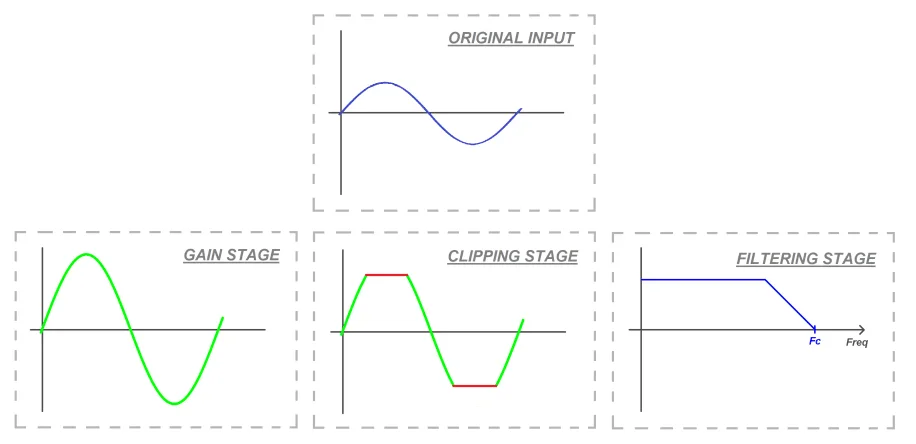
Gain effect pedals’ main purpose is to make your sound louder by the use of amplifiers. Amplifier circuits can be built using JFET transistors, BJT transistors or Operational Amplifiers. The gain stage is very similar in all of the pedals, and only the amount of gain varies.
After the amplification, in most pedals there’s also a clipping of the signal: it’s in this point where the distortion is added. Depending on whether it’s a soft booster or a crazy fuzz the clipping will be more or less aggressive. This stage is one of the principal differences between the different gain pedals.
Once the signal has been clipped, most pedals include a filter stage that lets you shape the tone. Some consist of a single low pass filter that sets the high frequency cutoff while others have low, mid and highs knobs.
2 – The gain stage
In this stage the signal is boosted through an amplifier circuit. To understand this stage we’ll use some of the actual circuits present in real world effect pedals.
2.1 – Operational Amplifier gain stage
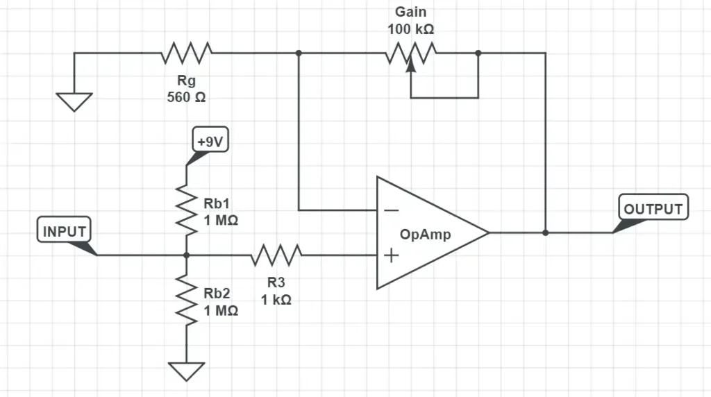
The circuit we’ll use in this case is a slightly simplified version of the gain stage in the Rodent Distortion effect pedal.
To better understand it we highly recommend you to check our Operational Amplifier series of posts, where you can find the basic theory behind these devices along with detailed circuit analysis.
In this case the opamp is set as a negative amplifier with a gain determined by the ratio between the potentiometer and the gain resistor Rg.
2.2 – JFET gain stage
This gain stage is from the Samurai Booster effect pedal. Now, the amplifier is built using a JFET transistor. Be sure to check our JFET posts if you want to learn more about JFET transistor circuits!
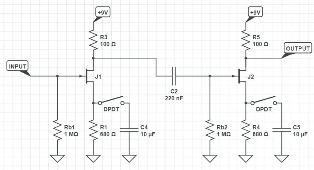
In this case, the circuit has two identical stages where the gain is set by the DPDT (high level gain or low level gain). After that, the volume can be fine tuned with the output volume potentiometer.
2.3 – BJT gain stage
Another gain stage you can find in effect pedals is the BJT amplifier. Because of its low input impedance, many times JFET are preferred over BJTs. Nevertheless you can find this particular gain stage especially in fuzz effect pedals like the Big Muff Pi.
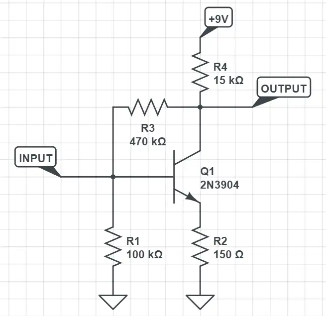
This is one of the four BJT gain stages in the Big Muff Pi pedal. While the values of the components vary slightly between different Big Muff Pi versions, the structure of the gain stage remains the same.
3 – The clipping stage
To produce distortion in the signal, a clipping is applied to the signal. It’s called like this because it literally chops the top and bottom of the signal once they exceed a particular threshold. Clipping can be achieved through two main techniques:
3.1 – Exceeding the maximum voltages of the amplifier stage.
In an opamp the output voltage always remains between the power margins. That means that a 0-9V powered opamp can only output signals within 0 and 9V. This also happens in transistor-based gain stages.
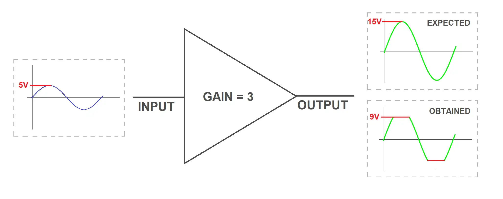
For example, imagine an input signal with an amplitude of 5V, an opamp amplifier with a gain of 3 and a standard power supply of 9V. Even if the theoretical output signal should have an amplitude of 15V (5·3), as the output of an operational amplifier [ must always remain within the power margins ] the signal will be chopped at 9V. This will produce a clipping that depends highly on the IC used and can colour the tone: a TL072 will produce a different clipping than a JRC4558. This technique is not used a lot as it depends too much on the opamp used and is not very pleasant to the ear.
3.2 – By the use of clipping diodes.
Many times diodes are replaced by other kind of devices that act the same way:
- LEDs act just like a diode: they just let the current flow in the forward direction and have a forward voltage (Vd). The only main difference is that they produce light, which can be used as a visual indicator on how much clipping is being produced!
- JFETs can be wired as a diode by reversing how the pins are connected (they’re just a PN junction!).
- BJTs also have a PN junction, so they can also be used as clipping devices.
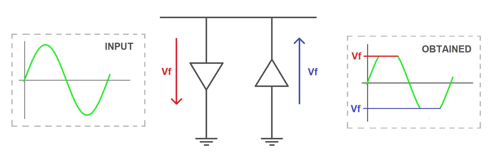
Until the signal reaches the forward voltage, the diode acts like an open switch: the output signal is the same as the input voltage (green). But as soon as the input signal exceeds the forward voltage, the diode turns on and forces the constant forward voltage. This happens on both the positive swing (red) negative swing (blue).
4 – Differences between effects
4.1 – Boosters
The main task of a booster pedal is to take the input sound signal and amplify it at a higher level. As distorting the signal in any way is not the purpose of booster effects we can classify them in two groups:
- Clean boosters like the Samurai Booster, that replicate your sound at a louder volume but don’t introduce any kind of distortion
- Boosters that, besides of the increased volume, also add a bit of saturation to the signal. An example is the Rangemaster Treble Booster, that adds a little overdrive at higher output volumes.
4.2 – Overdrives
Overdrive pedals emulate the saturation produced by valves in a tube amp. They tend to produce warmer and creamier tones than distortion pedals, making them very suitable for rock and blues. The TubeScreamer is probably the most known overdrive effect pedal: it has been used for decades and still remains one of the references.
Overdrives usually have three knobs:
- Gain: sets the amount of amplification of the pedal.
- Tone: usually a high pass filter that controls the amount of high frequencies in the sound.
- Volume: sets the overall output volume of the pedal.
The way overdrives produce gain is slightly different than distortion pedals: warm and subtle overtones are achieved at quieter volumes, but the distortion turns harsher as the volume increases.
Overdrive pedals are many times used in front of a tube amp, pushing it harder to obtain a natural overdrive. For example, one of the TubeScreamer applications is placed in front of the amp with the volume all the way up and the gain all the way down.
4.3 – Distortions
When compared with overdrives, distortion pedals produce a much more aggressive sound. Their amplification stages have higher gain values and the clipping is harder, resulting in a more saturated sound.
Distortions produce practically the same amount of distortion no matter what the volume is, and also have a three knob control system most of the times (Gain, Tone and Volume).
4.4 – Fuzz
Fuzzes present the maximum amount of clipping and distortion, producing harsh and unnatural tones. In many cases, this sound is achieved using non-standard bias resistors or inverting transistor polarities among other unorthodox techniques.
One curiosity to point out is that fuzz pedals are almost only built using discrete transistors and not opamps. As we discussed in this post, operational amplifiers are more stable and controlled than transistors and in this case, we want to get all the distortion and instability we can get!