Diodes & LEDs, Effect Pedal Circuits, Electronic Components, Electronics Tutorials
Electronics Tutorials: Diodes and LEDs (II)
In the introduction post about LEDs and diodes we covered what is a semiconductor material and how diodes and LEDs work. Now we’ll use them to build some common circuits you can find in effect pedals.
1 – Current protection
In this simple circuit we’ll limit the current that flows through the diode with a limiting resistor. The diode (or LED) doesn’t have the ability to limit the current flow; once it’s forward biased it will let through all the current available.
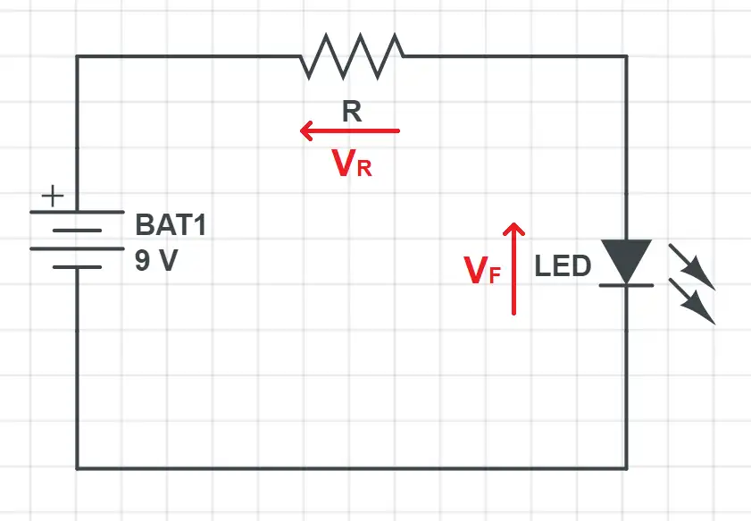
Diode and LED applications: LED current protection with limiting resistor
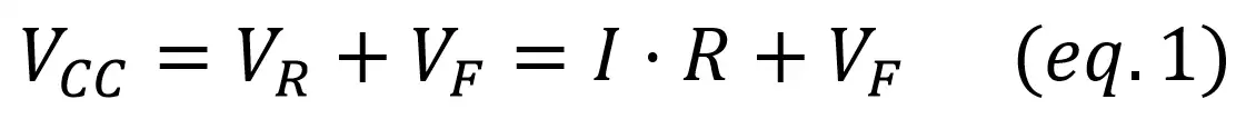
That’s why an external limitation is needed: as you’ll remember from our first post about diodes this kind of device has a maximum current they can let through without burning. With a resistor we avoid exceeding this limit, preventing any damage to the diode or LED. This protection is found in the On/Off diodes of your effect pedal kits. For this example we’ll use: – A blue LED (Vf = 2.8~3.5) with a maximum current of 15mA – A standard input voltage of 9V (the most common in effect pedals) Our mission now is to find the resistor that ensures that no more than 10mA of current will flow through the LED. We use 10mA instead of 15mA to have a safety margin: resistors have tolerances, the power could have small fluctuations… From Kirchoff’s voltage law,
What values do we pick for the current and Vf? Here’s where the designer work starts! This is how you should approach these questions: – Maximum current through the circuit. In our LEDs maximum current is limited to 15-20mA, so you have to pick anything below that value. We’ll stick to 10mA to stay safe, as brightness doesn’t vary that much once a minimum current value has been exceeded. – Forward voltage. Vf in LEDs and diodes often vary through a range, and two different LEDs of the same color will probably have different Vf values. In our case, Vf = 2.8~3.5V. Which value do we choose then? The “correct” solution would be to measure our LED to be 100% sure of the Vf value, and then use it in our calculations. But as this is impractical in real life, you always have to consider the worst case. In this circuit, “worst case” means the case in which more current is flowing, as it can damage our LED. This worst case will happen when the Vf is the minimum (2.8V), as Vcc – Vf will be maximum.
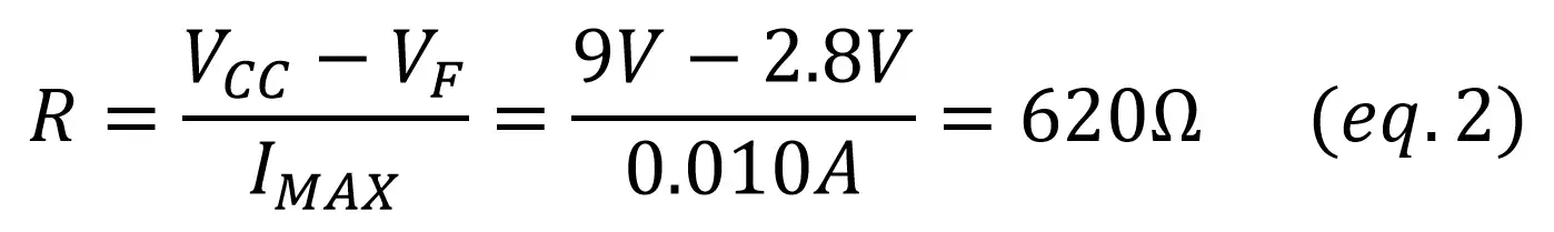
As we want to ensure that 10mA is the maximum value, we’ll have to grab a resistor of 620 Ohms or more, as with a higer value resistor less current will flow (if you need a more detailed explanation check out our resistor post!).
2 – Current direction control
Imagine you want the current to flow in just one direction. A diode comes in handy for this situation as it blocks the current in one way and lets it pass in the other.
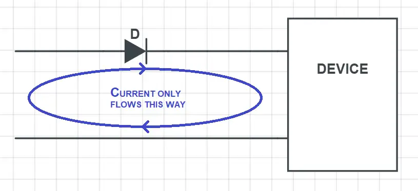
This kind of solution is commonly used to protect a device against inverted polarity, to create a rectified signal from an AC input or to create the envelope that controls an autowah from the input volume. The only drawback is that the diode has a forward voltage, so there’s a small voltage drop that has to be considered when designing the circuit. For example, if used as a inverted polarity protection and the device is fed with a 9V DC power signal, the output will be ~8.3V instead of the 9V as we have to substract the forward voltage of around 0.7V for silicon diodes.
3 – Clipping diodes
Diodes also play a crucial role in overdrive and distortion pedals: they are in most cases in charge of producing the clipping of the signal. To understand how they work we’ll take a look at a simplified version of our opamp buffer. If you want to read more about operational amplifiers we recommend you this post.
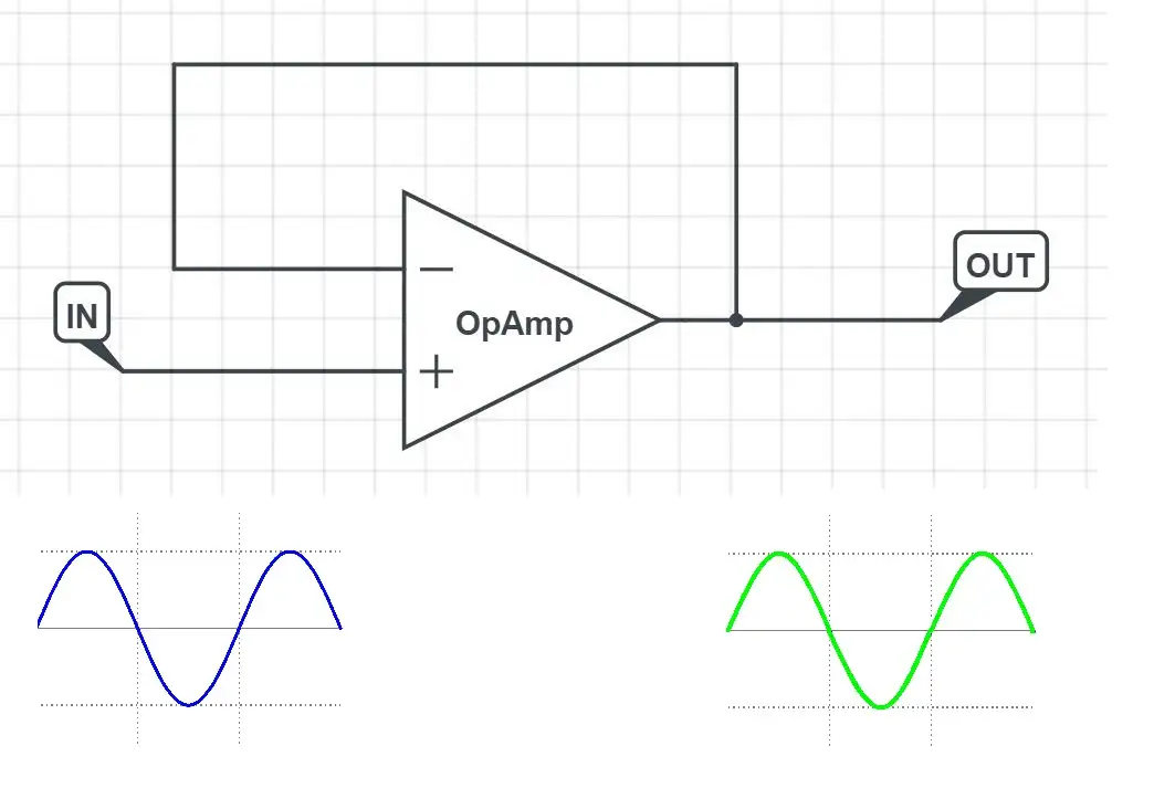
Diode and LED applications: Basic Opamp buffer circuit
With this kind of amplifier we have a replica of the input signal in the output, as you can see in the previous schematic. If we add two clipping diodes the output changes: – If the signal is lower than the forward voltage of the diode, it will act as an open switch and the input signal is replicated at the output – If the signal is higher than the forward voltage, the diode acts as a closed switch with a voltage drop of Vf. The result is that the diode will “cut” or clip any part of the signal higher than Vf. As we place one diode in each direction, the clipping happens both on positive and negative swings. This is the principle behind overdrives and distortions: the amplifier boosts the signal until it becomes higher than the forward voltage. A higher signal will then be more clipped, producing more distortion.
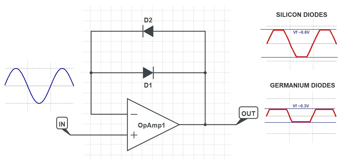
Opamp buffer with clipping diodes[/caption> Germanium diodes have a lower forward voltage: that’s why they clip at a lower level and produce a different tone than silicon diodes. If you want to test the difference between both clipping styles we recommend you our UBE Screamer Kit: the circuit includes both germanium and silicon diodes and a jumper to switch between them so you can try different settings and use the one you prefer.