Electronic Concepts
The truth behind electronic component values
If you’ve been into electronics for some time you’re probably aware of the odd values many components have: why 47Ω and 91kΩ resistors, and not 50Ω and 100kΩ? In this short post we explain the mystery behind these numbers!
1 – A bit of history
When you’re looking for 330uF capacitor for design, you’ve probably wondered why this value. Wouldn’t it be easier to use more “rounded numbers”, like 300uF? To answer this question we need to go back to the beginning of the 20th century.
At that time component values were way different than they are now. As there was no such high demand for electronics, most of them had specific values depending on the application they were to be used into: you needed a component of a specific value, you went straight to the manufacturer and he had it made for you. A low production model was sustainable for some time, but then something happened that changed electronics forever.
In the 1950s took place one of the greatest inventions of the 20th century: the transistor. With this small device came a whole new world of possibilities, and consumer electronics demand kicked off. The customized low production volume was no longer sustainable, mainly because of two reasons:
- As more and more devices were required it was necessary to start mass producing them to lower the costs, otherwise it would be impossible to deliver consumer goods at a reasonable price. This meant picking some “standard” values, making designers adapt their electronic circuits to stick to them.
- Nowadays we can produce components with a very tight deviation from the expected value. This deviation is what we call tolerance. Back then tolerance values were way higher, which made some component values unnecessary. The next example will illustrate this concept: if three resistors of 9k, 10k and 11k have a 20% tolerance, that means they can swing from 7.2k~10.8k, 8k~12k and 8.8k~13.2k. The next picture shows these values and how they overlap between each other:.
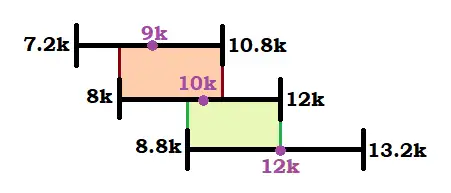
What’s the point of choosing between a 9k or a 10k resistor with a 20% tolerance, if in the end their value will be approximately in the same range? Or picking a 12k resistor with a value that may even fall in the same range than our 9k resistor?
These problems lead to choosing some “preferred numbers” and stick to them. And as you can probably imagine, component tolerance has a huge importance on which values were chosen!
2 – The E Series
The only logical thing to pick those “preferred numbers” would be to pick values which ranges don’t overlap.
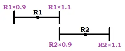
Let’s do this starting with a value of R1 = 10k, and considering a 10% tolerance. For the next value, R2, not to overlap with R1, its lower value (R2 – 10% = R2 x 0.9) should be equal to R1’s maximum possible value (R1 + 10% = R1 x 0.1) in order not to let any gap in between:
If we do some maths,
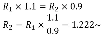
So to get the next value we only have to multiply by 1.22 the previous number. Easy, right? Lets this and see what we get!

This value should ring a bell to you… What about the next ones?
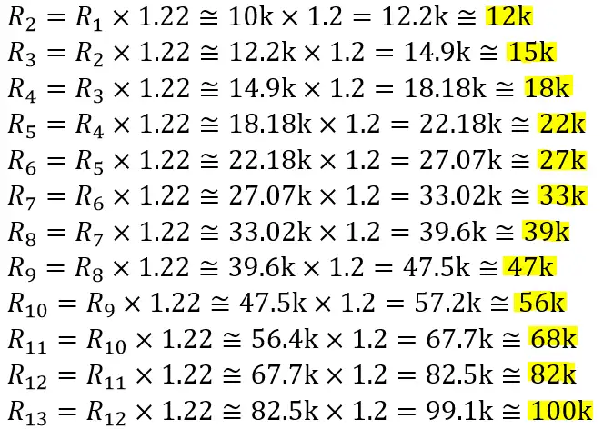
By doing this for each one we get all 12 values between 10 and 100. These are the 12 values of the E12 E-series! After 100 we’ll get the same values in the next octave (100, 120, 150…). The same happens if we start with one (1, 1.2, 1.5…).
There is two important curiosities that are consequence of this way of obtaining the preferred numbers:
- as we have to multiply the previous value by a fixed number, we don’t get a linear distribution but a logarithmic one.
- any ratio of two consecutive values will be ~1.2. For example, 12/10 = 1.2, 15/12 = 1.222, 18/15 = 1.2 and so on
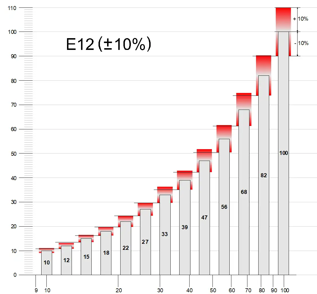
Choosing these values we avoid any overlap between a part value and the next one. One could do the same exercise with any of the E-series (E3, E6, E24…). This would lead to the following table, in which tolerance and base values of the most common E-Series are indicated:
| E-Series | Tolerance | Base values |
|---|---|---|
| E6 | 20% | 1.0, 1.5, 2.2, 3.3, 4.7, 6.8 |
| E12 | 10% | 1.0, 1.2, 1.5, 1.8, 2.2, 2.7, 3.3, 3.9, 4.7, 5.6, 6.8, 8.2 |
| E24 | 5% | 1.0, 1.1, 1.2, 1.3, 1.5, 1.6, 1.8, 2.0, 2.2, 2.4, 2.7, 3.0, 3.3, 3.6, 3.9, 4.3, 4.7, 5.1, 5.6, 6.2, 6.8, 7.5, 8.2, 9.1 |
| E48 | 1% | 1.00, 1.05, 1.10, 1.15, 1.21, 1.27, 1.33, 1.40, 1.47, 1.54, 1.62, 1.69, 1.78, 1.87, 1.96, 2.05, 2.15, 2.26, 2.37, 2.49, 2.61, 2.74, 2.87, 3.01, 3.16, 3.32, 3.48, 3.65, 3.83, 4.02, 4.22, 4.42, 4.64, 4.87, 5.11, 5.36, 5.62, 5.90, 6.19, 6.49, 6.81, 7.15, 7.50, 7.87, 8.25, 8.66, 9.09, 9.53 |
Usually E24 and E48 are used for resistors (1% and 5% tolerance) and small capacitors, while E12 is preferred for electrolytic capacitors as they tend to have a bigger tolerance margin.
